How far a link reaches is set by five variables together: transmit power, antenna gain, receiver sensitivity, band attenuation, and line-of-sight/interference — lifting only one usually changes nothing.
High gain means a narrower beam: energy is concentrated, but both ends must be aimed more precisely, which raises install and maintenance effort.
Point-to-point backhaul and wide-area access are two different designs — decide first whether you are linking two fixed points or covering an area, then choose the antenna and band.
Models in this category
View all 216 models →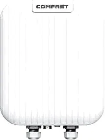
CF-WA971
Outdoor Wireless AP CF-WA971 with 3600Mbps wireless rate and 2.4/5.8GHz dual-band, supports IEEE802.11a/b/g/n/ac/ax/be, Directional Antenna, dimensions 285*215*73mm, POE (48V/0.5A), for parks, scenic areas, industrial parks and other outdoor coverage.
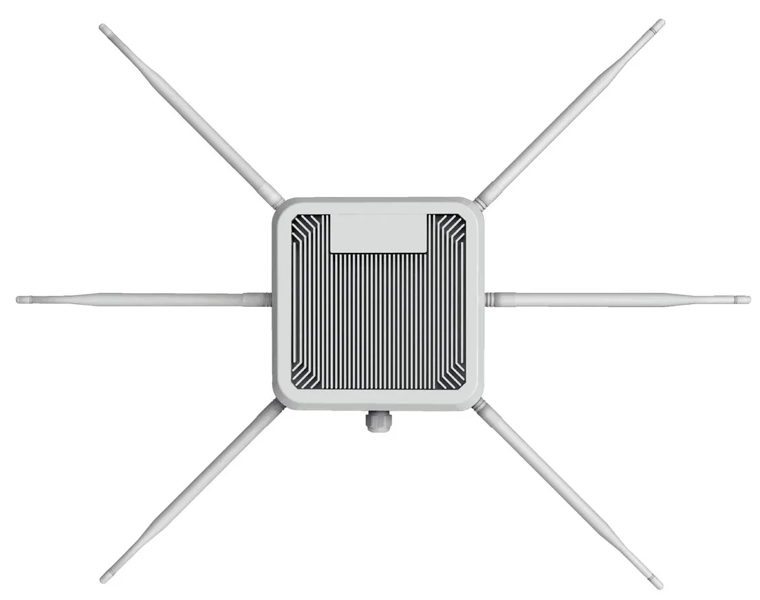
HW-621G-ME-01
Outdoor Wireless AP HW-621G-ME-01 with 3000Mbps wireless rate and 2.4GHz and 5.8GHz dual-band, supports IEEE802.11ax (Wi-Fi 6), external 6 7dbi high gain fiberglass omnidirectional antennas, dimensions Ø60*475*70mm, 48V PoE (up to 100m), for parks, scenic areas, industrial parks and other outdoor coverage.
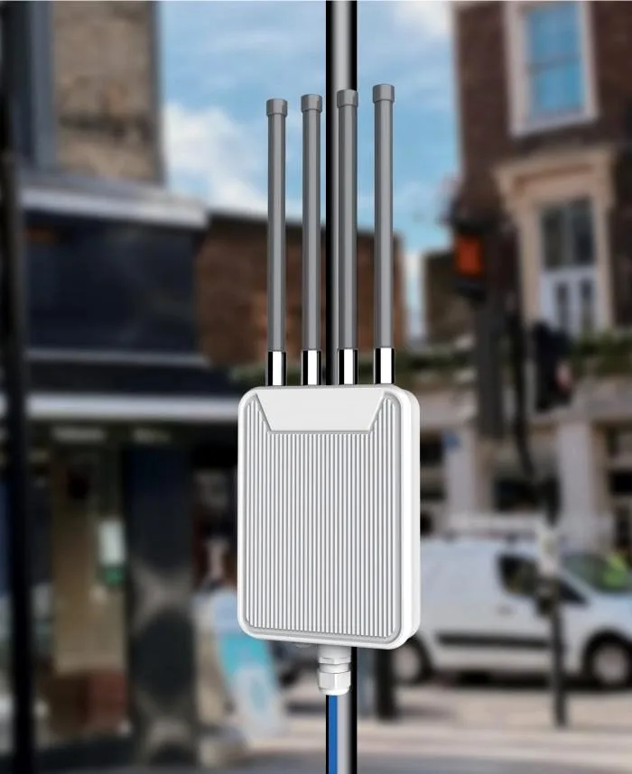
HW-621H-RE-01
Outdoor Wireless AP HW-621H-RE-01 with 3000Mbps wireless rate and 2.4GHz and 5.8GHz dual-band, external 4 7dbi high gain fiberglass omnidirectional antennas, dimensions Ø60*475*70mm, 48V PoE (up to 100m), for parks, scenic areas, industrial parks and other outdoor coverage.
CF-E120A V3
Wireless Bridge / CPE CF-E120A V3 with 300Mbps wireless rate and 5.8GHz dual-band, supports IEEE802.11b/g/n, bulit in 5.8Ghz: 11dBi Antennas, dimensions 165*95*51mm, for point-to-point links between buildings, cranes and elevators.
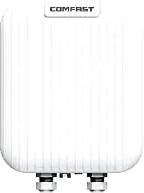
CF-E173BE
Wireless Bridge / CPE CF-E173BE with 3600Mbps wireless rate and 2.4/5.8GHz dual-band, supports IEEE802.11a/b/g/n/ac/ax/be, Directional Antennas 2.4G:11dBi 5G: 14dBi, dimensions 285*215*73mm, for point-to-point links between buildings, cranes and elevators.
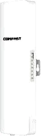
CF-E312A V2
Wireless Bridge / CPE CF-E312A V2 with 300Mbps wireless rate and 5.8GHz dual-band, supports IEEE802.11b/g/n, bulit in 2*14dBi Antennas, dimensions 262*80*53mm, for point-to-point links between buildings, cranes and elevators.
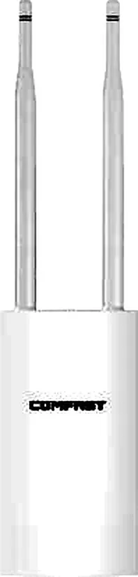
CF-EW71 V2
Outdoor Wireless AP CF-EW71 V2 with 300Mbps wireless rate and 2.4GHz single-band, supports IEEE802.11b/g/n, External 2*5dBi, dimensions 353*85*44mm, 48V 0.32A POE Power Adapter, for parks, scenic areas, industrial parks and other outdoor coverage.
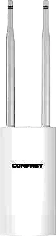
CF-EW72 V2
Outdoor Wireless AP CF-EW72 V2 with 1200Mbps wireless rate and 2.4/5.8GHz dual-band, supports IEEE802.11a/b/g/n/ac, External 2*5dBi, dimensions 353*85*44mm, 48V 0.32A POE Power Adapter, for parks, scenic areas, industrial parks and other outdoor coverage.

CF-EW74 V3
Outdoor Wireless AP CF-EW74 V3 with 1200Mbps wireless rate and 2.4/5.8GHz dual-band, supports IEEE802.11a/b/g/n/ac, External 2*5dBi, dimensions 380*54mm, 48V 0.32A POE Power Adapter, for parks, scenic areas, industrial parks and other outdoor coverage.

CF-EW75 V2
Outdoor Wireless AP CF-EW75 V2 with 1200Mbps wireless rate and 2.4/5.8GHz dual-band, supports IEEE802.11a/b/g/n/ac, External 2*5dBi, dimensions 368*57*30mm, 24V 1A POE Power Adapter, for parks, scenic areas, industrial parks and other outdoor coverage.
CF-EW81
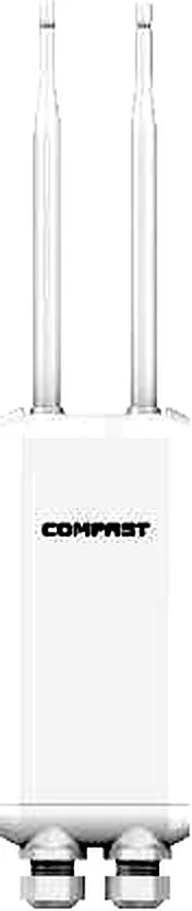
Outdoor Wireless AP CF-EW81 with 300Mbps wireless rate and 2.4GHz single-band, supports IEEE802.11b/g/n, External 2*5dBi, dimensions 90*388.2mm, 24V 0.5A POE Power Adapter, for parks, scenic areas, industrial parks and other outdoor coverage.

CF-EW82
Outdoor Wireless AP CF-EW82 with 1200Mbps wireless rate and 2.4/5.8GHz dual-band, supports IEEE802.11a/b/g/n/ac, External 2*5dBi, dimensions 210*51*34mm, 48V 0.32A POE Power Adapter, for parks, scenic areas, industrial parks and other outdoor coverage.
Related pages
01 Why reaching further is not solved by swapping in one high-gain antenna
- Transmit power and the EIRP ceiling: you cannot simply raise output. Most countries cap the overall EIRP (transmit power plus antenna gain minus cable loss); the higher the antenna gain, the lower the permitted transmit power often becomes — it is a redistribution of energy, not free amplification.
- Antenna gain: gain does not 'amplify' the signal; it gathers energy from unwanted directions into the main lobe. Off-axis directions get weaker and the coverage shape changes with it.
- Receiver sensitivity: a link is two-way. Shouting louder at one end is useless if the other cannot hear it; sensitivity sets the weakest signal that can still be decoded and is a property of the radio and baseband, not something you can raise later.
- Band and attenuation: the higher the frequency, the greater the free-space loss and the poorer the diffraction and penetration under equal conditions. 2.4 GHz reaches further and penetrates better but is more crowded; 5 GHz is cleaner and more interference-resistant but attenuates faster over the same budget.
- Line of sight and interference: terrain, buildings and tree canopies block or weaken the signal, and more co-channel APs nearby raise the noise floor and cut the usable distance. Sight lines and co-channel interference are the two things to confirm on site before choosing anything.
02 The five variables that set the distance
| Variable | What it governs | The cost of pushing it |
|---|---|---|
| Transmit power and EIRP cap | The usable output at one end of the link | Capped by regulation — exceeding it is non-compliant, and higher antenna gain forces power down |
| Antenna gain | Energy density in the main lobe | Higher gain narrows the beam, making aiming harder and coverage angle smaller |
| Receiver sensitivity | The weakest signal that can still be decoded | Fixed by the radio and baseband — cannot be raised after the fact |
| Operating band | Attenuation and penetration under equal conditions | 2.4 GHz goes further but is crowded; 5 GHz is cleaner but shorter |
| Line of sight and interference | The real usable margin | Depends on the site — only siting or extra margin can compensate |
These five are an AND, not an OR: whichever becomes the bottleneck, the whole link is stuck at that value.
03 The other side of high gain: narrow beams and the cost of aiming
- The higher the gain, the narrower the horizontal and vertical beam and the smaller the coverage angle: it is good at pushing energy in one direction, but no longer suits wide-angle area coverage.
- Two high-gain antennas must have their main lobes aimed at each other; a small offset drops the link budget quickly, so fine-tune against signal strength on site and lock the bracket once the peak is found.
- Brackets on poles or rooftops drift slowly under wind load, so the azimuth must be re-checked periodically, or the link quietly gets worse over time.
- High gain does not defeat obstruction: a narrow beam still cannot go around a building or dense foliage — the only fixes are raising the mounting point or adding a relay.
- Conversely, an omni antenna has a wide angle and forgiving aiming but lower gain at the same size, and radiating in all directions creates more co-channel interference. Use omni to cover an area; go directional only to link two fixed points.
04 Point-to-point backhaul versus wide-area access: two different designs
| Aspect | Point-to-point / multipoint backhaul (PTP / PTMP) | Wide-area access |
|---|---|---|
| Goal | Join two or more fixed points wirelessly as a backbone | Let user devices across an area connect and get online |
| Antennas | Directional at both ends, main lobes aimed at each other, higher gain for more distance | Omni or sector, aiming for angular coverage and evenness |
| What 'distance' means here | As far as possible and as stable as possible | Enough radius — the priority is no dropouts and adequate capacity |
| Gain preference | Prefer higher gain, paired with precise aiming | A sensible gain and pattern is enough — no need to chase extremes |
| Main risk | Aiming precision, wind drift, obstruction | User distribution, co-channel interference, per-AP capacity limits |
| Typical scene | Backbone between buildings or across a campus, remote-point backhaul | Area coverage for campuses, camps, yards and scenic sites |
05 Choosing the band: the 2.4 GHz versus 5 GHz distance trade-off
- At equal power and antenna, 2.4 GHz travels further and diffracts and penetrates better — a good fit when you need maximum reach with plenty of obstruction.
- 5 GHz offers wider, cleaner spectrum with less interference and easier high throughput, but its usable distance under equal conditions is clearly shorter than 2.4 GHz.
- Using 2.4 GHz for edge coverage and 5 GHz for nearby high bandwidth is a common split — do not expect 5 GHz alone to carry a long haul.
- For a remote point that only needs low-bandwidth backhaul, 2.4 GHz is often easier to make stable than 5 GHz.
- The final band and channel choice must also comply with the local spectrum and power rules and avoid frequencies already in use on site.
06 Testing and tuning: how to tell whether the link will hold
- Do a sight-line survey before siting: confirm a clear path visually, or with both ends temporarily raised to mounting height, keeping terrain, buildings and canopies out of the sight line.
- After power-up, check the wired side first: confirm power and port negotiation, ruling out a 'weak signal' that is really a drop-out, an over-long cable or a mismatched power standard.
- Judge the margin first from received signal strength and signal-to-noise ratio, then look at errors, retries and negotiated rate; the margin must also absorb rain fade, growing foliage and daily variation.
- Measure throughput and loss at the most remote point and under the worst real conditions — not just where it looks good near the equipment room.
- On a directional link, tune while watching the signal: adjust azimuth and downtilt step by step, lock the bracket at the peak, and record the angles as a baseline for later checks.
- Record the field data (signal strength, SNR, channel, negotiated rate, loss) in the handover document so there is a basis to compare when dropouts appear later.
07 Real models: coverage and backhaul for long distances
| Model | Type | Rate | Band | Antenna | Power | IP |
|---|---|---|---|---|---|---|
| CF-EW71 V2 | Outdoor AP (coverage) | 300Mbps | 2.4GHz | External 2×5dBi | 48V 0.32A PoE | IP66 |
| CF-EW72 V2 | Outdoor AP (coverage) | 1200Mbps | 2.4/5.8GHz | External 2×5dBi | 48V 0.32A PoE | IP66 |
| CF-EW75 V2 | Outdoor AP (coverage) | 1200Mbps | 2.4/5.8GHz | External 2×5dBi | 24V 1A PoE | IP66 |
| CF-WA971 | Outdoor AP (directional) | 3600Mbps | 2.4/5.8GHz | Directional antenna | 48V 0.5A PoE | IP67 |
| HW-621G-ME-01 | Outdoor AP (coverage) | 3000Mbps | 2.4/5.8GHz | External 6×7dBi omni | 48V PoE | IP67 |
| HW-621H-RE-01 | Outdoor AP (coverage) | 3000Mbps | 2.4/5.8GHz | External 4×7dBi omni | 48V PoE | IP67 |
| CF-E120A V3 | Bridge/CPE (backhaul) | 300Mbps | 5.8GHz | Built-in 11dBi | PoE | IP65 |
| CF-E312A V2 | Bridge/CPE (backhaul) | 300Mbps | 5.8GHz | Built-in 2×14dBi | PoE | IP65 |
| CF-E313AC V2 | Bridge/CPE (backhaul) | 900Mbps | 5.8GHz | Built-in 2×14dBi | PoE | IP65 |
| CF-E317A | Bridge/CPE (long-haul) | 300Mbps | 5.8GHz | External 24dBi | PoE | IP65 |
| CF-E173BE | Bridge/CPE (backhaul) | 3600Mbps | 2.4/5.8GHz | Directional 2.4G:11dBi / 5G:14dBi | PoE | IP67 |
| CF-E319A V3 | Bridge/CPE (long-haul) | 900Mbps | 5.8GHz | External 26dBi | PoE | IP65 |
Figures are taken from this site's product data and cover only link-category dimensions; how far coverage or backhaul reaches depends on line of sight, environment and antenna configuration and must be assessed on site — defer to the unit nameplate and datasheet.
Questions
Q1 Does fitting a high-gain antenna clearly extend the range?
Not necessarily. Distance is set by transmit power, antenna gain, receiver sensitivity, band attenuation and line of sight together. A higher-gain antenna may force transmit power down to stay within EIRP limits, so the net effect is limited — and if the bottleneck is obstruction or sensitivity, the antenna swap does almost nothing. Run a link budget and a site survey first.
Q2 Is a higher-gain antenna always better?
No. Higher gain means a narrower beam, a smaller coverage angle and more demanding aiming. It suits point-to-point links where the direction is fixed; for covering an area a narrow beam leaves large blind spots and is worse than an omni or sector antenna at a sensible gain.
Q3 Can I use a high-gain directional antenna to cover an area?
Usually not worth it. A directional antenna compresses energy into one direction and falls off quickly off-axis, leaving blind spots. Area coverage suits omni or sector antennas better: moderate gain and an even pattern that still serves scattered users.
Q4 Both ends are aimed correctly — why is the distance still short?
A few common causes: an obstruction or an occupied Fresnel zone in between; transmit power limited by the EIRP cap or turned down; 5 GHz chosen for a long, congested path; insufficient sensitivity to decode a weak signal; or mismatched antenna polarisation. Working through them usually finds the bottleneck faster than adding more gain.
Q5 How should a long link be tested properly?
Confirm the sight line first, then check power and port negotiation to rule out a false 'weak signal'; read the margin from signal strength and SNR, corroborate with errors/retries and negotiated rate; finally measure throughput and loss at the remote worst case and in the worst weather, and document the angles and readings. Never stop at a good result next to the equipment.
Tell us the site conditions — distance between the two ends, mounting height, obstructions, power location and local regulatory requirements — and we will recommend long-distance coverage and backhaul options from the multi-brand range we supply. For backhaul schemes see /wireless-bridge/, for antenna fundamentals and the gain-versus-beam relationship see /knowledge/antenna-types/, and for outdoor model selection see /access-point/outdoor-access-point/.