Point-to-point uses one pair; point-to-multipoint uses one hub serving several remotes
Line of sight comes first: keep at least about 60% of the first Fresnel zone clear
Prefer 5.8 GHz for long spans and noisy sites; choose 2.4 GHz only when you must diffract or penetrate
A point-to-point wireless link between two buildings: one pair of directional units instead of a cable run
Models in this category
View all 216 models →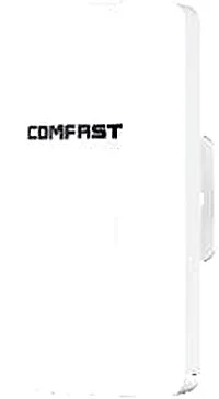
CF-E120A V3
Wireless Bridge / CPE CF-E120A V3 with 300Mbps wireless rate and 5.8GHz dual-band, supports IEEE802.11b/g/n, bulit in 5.8Ghz: 11dBi Antennas, dimensions 165*95*51mm, for point-to-point links between buildings, cranes and elevators.
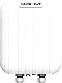
CF-E173BE
Wireless Bridge / CPE CF-E173BE with 3600Mbps wireless rate and 2.4/5.8GHz dual-band, supports IEEE802.11a/b/g/n/ac/ax/be, Directional Antennas 2.4G:11dBi 5G: 14dBi, dimensions 285*215*73mm, for point-to-point links between buildings, cranes and elevators.

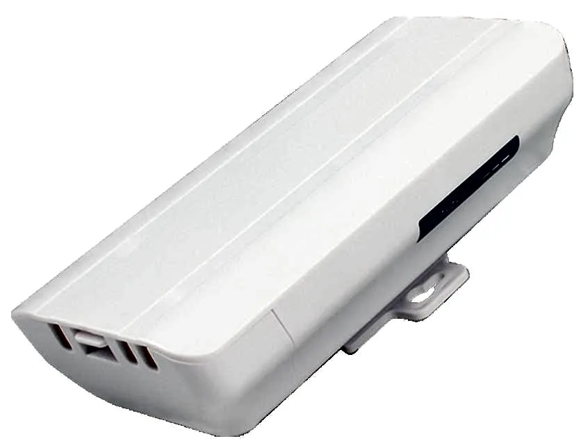
CF-E312A V2
Wireless Bridge / CPE CF-E312A V2 with 300Mbps wireless rate and 5.8GHz dual-band, supports IEEE802.11b/g/n, bulit in 2*14dBi Antennas, dimensions 262*80*53mm, for point-to-point links between buildings, cranes and elevators.
BS-300D
Wireless Bridge / CPE BS-300D with 300Mbps wireless rate and 2.4G single-band, 24V PoE, for point-to-point links between buildings, cranes and elevators.
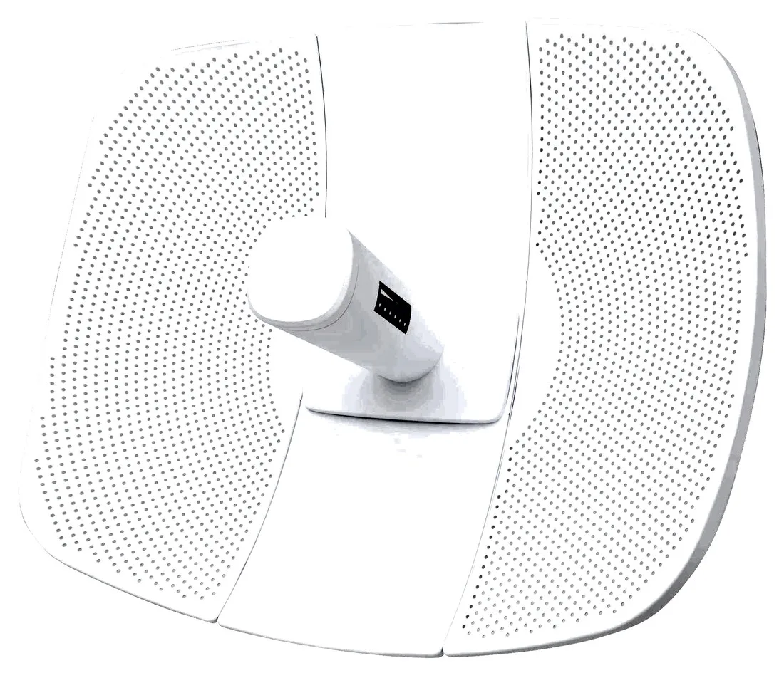
BS-500L
Wireless Bridge / CPE BS-500L with 300Mbps wireless rate, dimensions 395*340*250mm, 24V PoE, for point-to-point links between buildings, cranes and elevators.
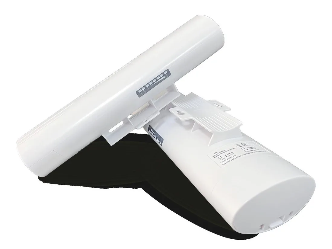
BS-500T
Wireless Bridge / CPE BS-500T with 300Mbps wireless rate, 24V PoE, for point-to-point links between buildings, cranes and elevators.
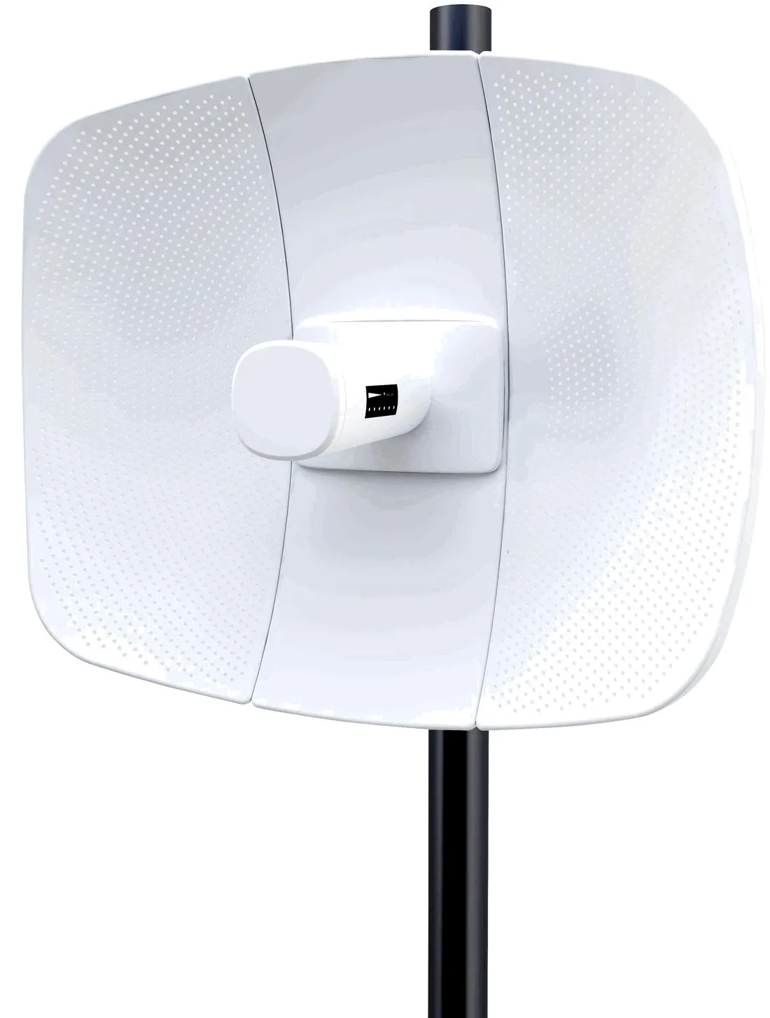
BS-560L
Wireless Bridge / CPE BS-560L with 900Mbps wireless rate, dimensions 395*340*250mm, 24V PoE, for point-to-point links between buildings, cranes and elevators.
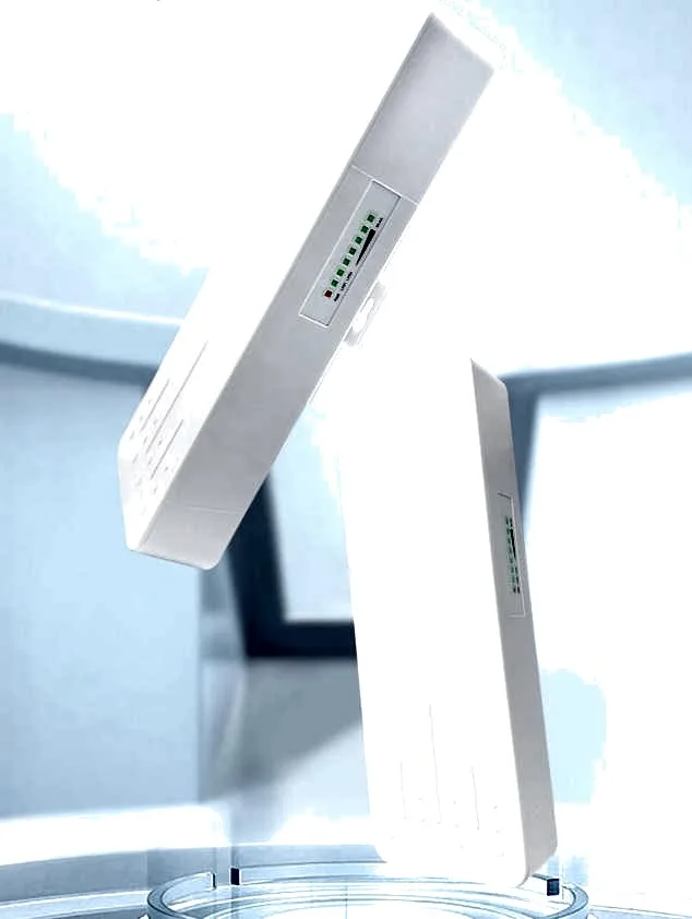
BS-900
Wireless Bridge / CPE BS-900 with 900Mbps wireless rate, dimensions 250*90*60mm, 24V PoE / 12V DC, for point-to-point links between buildings, cranes and elevators.
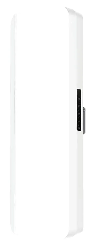
BS-900D
Wireless Bridge / CPE BS-900D with 900Mbps wireless rate, 24V PoE / 12V DC, for point-to-point links between buildings, cranes and elevators.

BS-900G
Wireless Bridge / CPE BS-900G with 900Mbps wireless rate, 24V PoE / 12V DC, for point-to-point links between buildings, cranes and elevators.

BS-900M
Wireless Bridge / CPE BS-900M with 900Mbps wireless rate, 24V PoE / 12V DC, for point-to-point links between buildings, cranes and elevators.
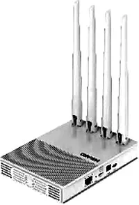
CF-E11
Wireless Bridge / CPE CF-E11 with 2.4GHz: 300Mbps wireless rate, External 4*5dBi antenna, dimensions 150*110*26mm Antenna: 175mm, for point-to-point links between buildings, cranes and elevators.
Related pages
01 What a wireless bridge is: a segment of cable replaced by radio
A wireless bridge uses two or a set of directional-antenna units to build a Layer-2 link between two network points that cannot be cabled. To the network above it behaves like a transparent cable: the switches, cameras and PCs at both ends sit on the same subnet and the IP plan needs no change. The usual form is a master/slave pair — one end connects to the local switch or router LAN port, the other to the far-side switch or device. Vendors often call these directional units CPEs or bridges, and the mode is usually either transparent bridging or gateway/NAT. Use transparent bridging for building-to-building interconnect so both ends merge into one LAN; use gateway mode to bring a few standalone devices online. The point matters: a bridge answers 'is the link up', while terminal wireless coverage is a separate job — often finished with APs at the far end.
02 Four common topologies
- Point-to-point (P2P): one master/slave pair, each end wired to a switch, joining two fixed points into a single link — the most common case for building-to-building or room-to-building links.
- Point-to-multipoint (P2MP): one hub serving several remotes, ideal when a single aggregation point feeds scattered sites, such as video backhaul from several small buildings in a campus. The hub capacity is shared, so the more remotes, the less each one gets.
- Relayed chain: when the two ends have no clear line of sight, add a relay pair at an intermediate visible point to hop the traffic across. Every hop adds latency and cuts usable bandwidth.
- Bridge plus coverage: the bridge only pulls the backbone to the far building; outdoor or indoor APs then provide local wireless there. Terminals do not connect to the bridge directly.
03 Line of sight and the Fresnel zone — the physics that decides the link
The first requirement is line of sight (LOS): the two antennas must be able to 'see' each other. But seeing is not enough — radio travels between the antennas as an ellipsoid called the Fresnel zone. The engineering rule is to keep at least about 60% of the first Fresnel zone clear; anything intruding into it (treetops, building corners, rooftops, cranes, even the ground nearby) brings attenuation, errors or a sharp drop in throughput. The zone's radius changes with distance and frequency — longer spans and lower bands make a fatter ellipsoid that demands more clearance. Long links should therefore be raised so the path grazes just above obstacles rather than hugging eaves or the ground, and should avoid branches that sway in the wind or cranes under construction. Separate three cases: full LOS is ideal; near-LOS (slight obstruction) needs extra margin; NLOS survives only through diffraction and reflection, with unreliable throughput and stability.
04 2.4 GHz or 5.8 GHz
| Aspect | 2.4 GHz | 5.8 GHz |
|---|---|---|
| Wavelength & diffraction | Longer wavelength: better diffraction and penetration, so a slight obstruction may still connect | Shorter wavelength: weaker diffraction, more sensitive to obstruction, needs a cleaner line of sight |
| Interference & channels | A shared band crowded by Wi-Fi, Bluetooth and microwaves; few clean channels | Relatively clean with more usable channels — good for campuses running many links at once |
| Antenna gain & size | Same gain needs a larger antenna; high-gain directional units are bulky | Higher gain in the same footprint; compact directional antennas suit long spans |
| Throughput | Limited by standard and interference; generally lower | Higher throughput at the same standard — the mainstream choice for bandwidth-hungry links |
| Typical use | Short range, slight obstruction, or a point needing penetration or diffraction | Long-span backbones, building-to-building or across a site, and video backhaul with many links |
Rule of thumb: use 5.8 GHz whenever you can; fall back to 2.4 GHz only when you must diffract, penetrate or reuse existing 2.4 GHz gear.
05 Antenna gain, link budget and range estimation
Antenna gain is not an amplifier — it only focuses energy in one direction, so higher gain means a narrower beam that is harder to aim. Whether a link works comes down to the link budget: transmit power + transmit antenna gain − free-space path loss + receive antenna gain − cable and connector loss, with enough margin left for rain fade, growing leaves and temporary obstructions. Free-space path loss grows with distance and frequency, so longer spans or higher bands need higher gain to compensate. One warning is essential: how far a bridge reaches depends on how clean the line of sight is, on-site interference, alignment quality and the gain at both ends — there is no universal distance number, and any real span must be assessed on site. What we provide is the right gain class and selection guidance; the achievable range is set by site conditions.
06 Bandwidth, latency and what the link can carry
A wireless link is a half-duplex shared medium: all traffic competes on the same radio, and the headline rate is a physical-layer figure. Real throughput is clearly lower, with the gap set by distance, interference, alignment and gain at both ends, so plan from measured results, never from the nominal figure. On latency, a single wireless hop adds millisecond-level delay that grows with load and retransmissions; each relay hop piles on more delay and further cuts usable bandwidth, so link directly whenever you can. Treat the bridge as a pipe: do not stack too many services on it and always keep headroom for peaks.
07 Alignment and commissioning: from mounting to a live link
-
1 ① Test up close first
Get the master and slave talking at short range first to confirm the mode, IP and credentials, then mount them high — it saves repeated trips up the ladder.
-
2 ② Coarse aim
Point both ends roughly at each other by compass bearing and elevation so the visual direction is right.
-
3 ③ Read the signal meter
Use the built-in alignment or signal-strength indicator and adjust slowly left/right and up/down while watching the reading.
-
4 ④ Optimise both axes before locking
Peak the signal on both the horizontal and vertical axes before fixing, so the link does not sit on a sub-optimal setting in one direction.
-
5 ⑤ Verify with real tests
Once linked, measure throughput and latency rather than trusting a full signal bar, and confirm with real traffic.
-
6 ⑥ Finish the install
Seal against water, add surge protection and earthing, fix the cable with a drip loop, and prevent drift or water ingress over time.
08 Typical scenarios: across buildings, across a site, and video backhaul
- Building-to-building backbone: when there is no way to run fibre or cut a chase, a bridge pair joins the two buildings' LANs into one.
- Across a factory site or campus: interconnect several buildings, warehouses and dormitories to the comms room, or use one hub for scattered points.
- Video backhaul: where cameras cluster at the perimeter, a junction, a crane or a field, a bridge carries the video back to the room without long cable runs.
- Hard-to-cable points: lift shafts, riverbanks or roadside positions that cable cannot practically reach.
- Temporary and construction: exhibitions, sites and temporary command posts that need a fast link and later teardown.
- Agriculture and scenic areas: backhaul between scattered points in orchards, farms and scenic sites.
09 Selection table (real models)
| Model | Band | Rate | Antenna | Rating · Power | Typical role |
|---|---|---|---|---|---|
| CF-E120A V3 | 5.8 GHz | 300 Mbps | Built-in 11 dBi | IP65 · <8 W | Light point-to-point, short to medium span |
| CF-E312A V2 | 5.8 GHz | 300 Mbps | Built-in 2×14 dBi | IP65 · ≤8 W | Mainstream point-to-point / multipoint |
| CF-E313AC V2 | 5.8 GHz | 900 Mbps | Built-in 2×14 dBi | IP65 · ≤8 W | Links needing higher bandwidth |
| CF-E317A | 5.8 GHz | 300 Mbps | External 24 dBi directional | IP65 · ≤8 W | Long-range directional (assess on site) |
| CF-E319A V3 | 5.8 GHz | 900 Mbps | External 26 dBi directional | IP65 · ≤12 W | Long-range, high-gain link (assess on site) |
| CF-E314N V2 | 2.4 GHz | 300 Mbps | Built-in 2×14 dBi | IP65 · <8 W | 2.4 GHz diffraction / fill-in |
| CF-E173BE | 2.4 / 5.8 GHz | 3600 Mbps | Directional 11 dBi (2.4G) / 14 dBi (5G) | IP67 · ≤24 W | High-bandwidth backbone (Wi-Fi 7) |
| CF-WA971 | 2.4 / 5.8 GHz | 3600 Mbps | Directional | IP67 · 48 V PoE · 2.5G port | High-bandwidth backhaul (outdoor AP used for bridging/backhaul) |
Band, rate, antenna and rating are taken from real product specifications on this site; the achievable distance depends on line of sight and the environment and must be assessed on site.
10 All-in-one bridges and how to choose
- All-in-one bridges (BS series): BS-300D, BS-500L, BS-500T, BS-560L and the BS-900 series, in 300 Mbps and 900 Mbps tiers, 24 V PoE, IP65 — suited to fast point-to-point pairs; exact band and specs are provided per model.
- Match the span and sight line: measure the distance and confirm line of sight and Fresnel clearance before choosing gain or deciding on a relay.
- Match the traffic: a few cameras suit the 300 Mbps tier; multiple HD streams or a backbone need 900 Mbps or more.
- Match the RF environment: go 5.8 GHz where 2.4 GHz is crowded; use 2.4 GHz only when you truly need diffraction or penetration.
- Match the mounting: unobstructed high points suit external high-gain directional antennas; restricted mounting and short spans suit integrated units.
- Match protection and power: outdoors, pick IP65/IP67 and surge-protected models, and use PoE for easy local power.
11 Deployment checklist
- Survey the line of sight on site, using binoculars or a drone if needed, to confirm first-Fresnel-zone clearance.
- Keep the bearing and elevation consistent at both ends to avoid a reversed or offset mount.
- Configure master/slave mode, IP and channel to plan, avoiding co-channel clashes with neighbouring links.
- Get the link working at short range before mounting high, to reduce repeated climbs.
- Measure throughput and latency and confirm they meet the service needs before handover.
- Seal against water, add surge protection and earthing, secure the cable and leave a drip loop.
- Record model, firmware, mounting position and configuration, and archive them at handover.
12 Further reading and next steps
- Antenna types and how to choose gain: /knowledge/antenna-types/
- Campus-wide coverage across multiple buildings: /solutions/campus/
- Choosing outdoor wireless APs: /access-point/outdoor-access-point/
Questions
Q1 Point-to-point or point-to-multipoint — which one?
Use point-to-point to join two fixed points; use point-to-multipoint when one aggregation point must serve several scattered sites. Remember the hub capacity is shared, so more remotes means less bandwidth each.
Q2 How far can a bridge reach?
There is no single answer. Reach depends on how clean the line of sight is, Fresnel clearance, on-site interference, antenna gain and alignment, and must be assessed on site. We recommend a matching gain class for your span but do not promise a distance.
Q3 Why is 5.8 GHz better than 2.4 GHz for long spans?
5.8 GHz suffers less interference, offers more channels and delivers higher gain in the same antenna size with a tighter beam, which suits a clean sight line. The trade-off is weaker diffraction and penetration, so heavy obstruction breaks it more easily.
Q4 Is a bridge link enough for latency and bandwidth?
A single wireless hop adds millisecond-level latency, usually fine for video backhaul and office interconnect; each relay hop adds latency and cuts bandwidth. Plan bandwidth from measured throughput, not the headline rate.
Q5 Can one model do both bridging and coverage?
A bridge handles the point-to-point or multipoint link, while terminal coverage is usually delivered by outdoor or indoor APs at the far end. Some outdoor APs can be used for bridging or backhaul, but it is best to select bridging and coverage separately for their own goals.
Send us the two locations, the span and your traffic needs, and we will propose a bridge link and alignment plan by model. Further reading: antenna types /knowledge/antenna-types/, campus coverage /solutions/campus/, outdoor APs /access-point/outdoor-access-point/.