At a Glance
System build
Wireless Bridge / CPE + Switch / Gateway / AC Controller
Key models
Requirements
5items
Acceptance checks
3items
Scenario Images
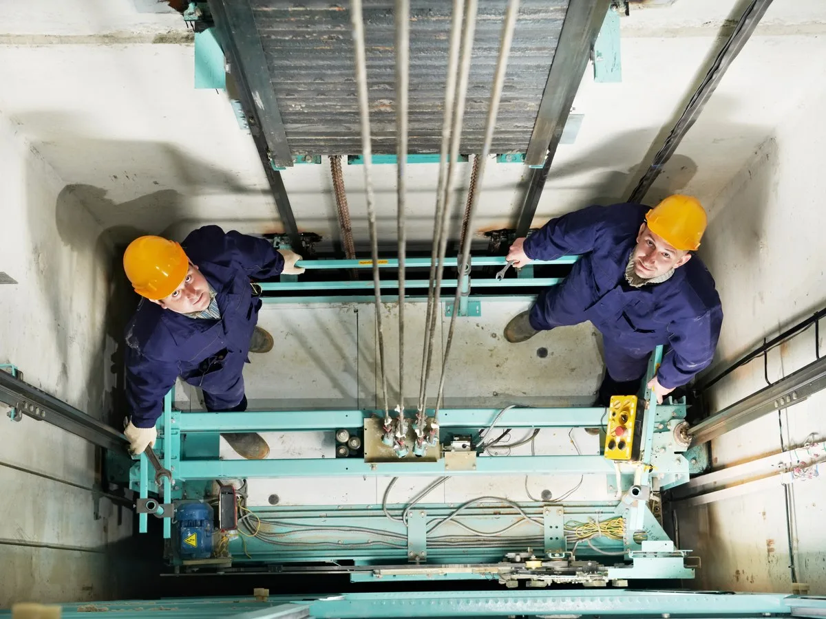
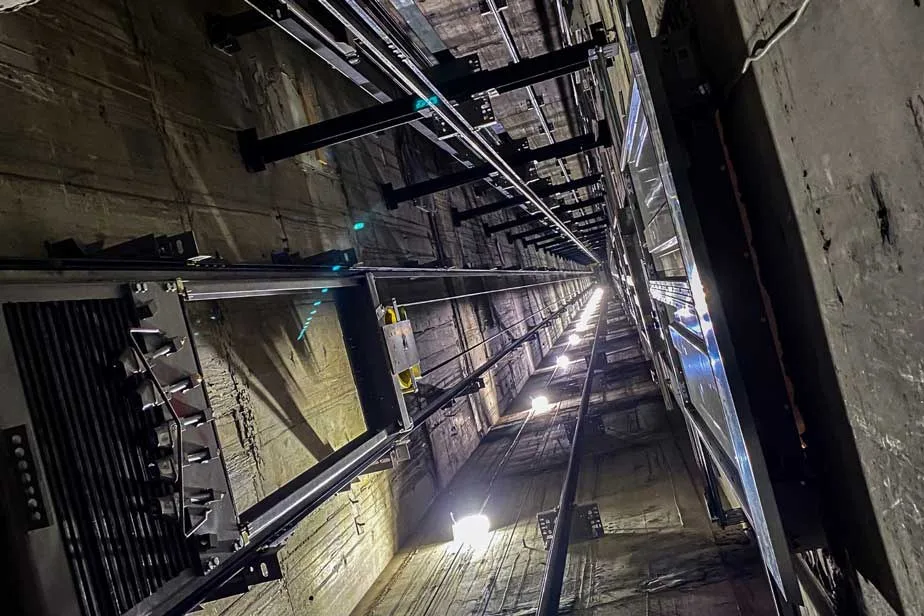
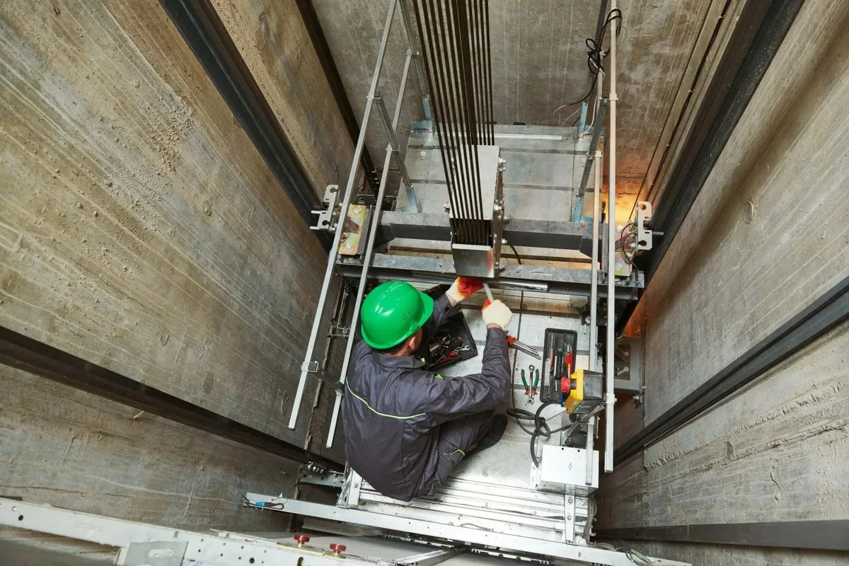
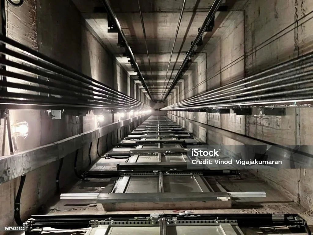
Key Pain Points
- No spare cores in the travelling cable — adding a camera means replacing the cable
- Inverter and traction noise in the shaft destabilises 2.4GHz links
- Commissioning falls to lift maintenance staff who are not network engineers
- The link comes and goes as the car travels in tall shafts
Solution Architecture
- Car side: the bridge mounts on the car top facing along the shaft, clear of the car structure
- Shaft side: the peer bridge forms a stable link, with a mid-shaft relay for tall shafts
- Band: mainly 5.8GHz, away from the 2.4GHz noise where inverters and traction machines sit
- Commissioning: LED pairing with no configuration, so maintenance staff can pair by indicator alone
- Backhaul: the shaft-side bridge lands on the equipment-room switch and NVR
On This Page
Requirement Breakdown
Figures below are design assumptions for sizing, not measured site data — confirm against the actual site before ordering.
- 01In-shaft transmission: lift cars rarely have spare cores in the travelling cable, so a wireless bridge replaces it.
- 02Bandwidth: about 2–4Mbps per lift camera, with the model chosen on aggregate bitrate where several lifts share a link.
- 03Power: where the car side has no convenient supply, the bridge can run on DC; the shaft head and pit follow site conditions.
- 04Set-up-free requirement: commissioning is often done by lift maintenance staff, so the hardware needs pairing without configuration.
- 05EMC environment: inverters and traction machines in the shaft create significant noise — survey before choosing a channel.
Zones & Topology
01
Car side: the bridge mounts on the car top with the antenna facing along the shaft, clear of car structure.
02
Shaft side: the peer bridge mounts opposite, forming a stable car-to-shaft link.
03
Head end: the shaft-side bridge runs on cable into the equipment-room switch and NVR.
04
Multiple lifts: one bridge pair per lift so links do not interfere with each other.
Standard Topology
Recommended Configuration
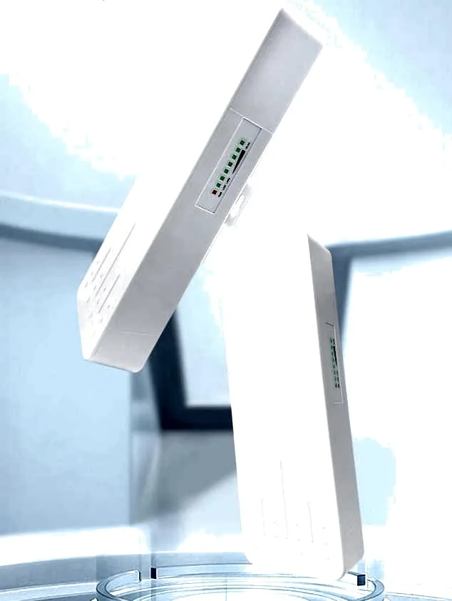 BS-900Wireless Bridge / CPE2 units per lift
5.8GHz bridge with LED pairing, set-up free — suited to shafts
View Details CF-E120A V3Wireless Bridge / CPE2 units per lift (short shafts)
300M 5.8GHz bridge for short shaft runs
View Details CF-SG53Switch / Gateway / AC ControllerPer comms room
5-port full-gigabit switch for bridges and NVR
View DetailsConfiguration list as a table
| Model | Quantity | Purpose |
|---|---|---|
| BS-900 | 2 units per lift | 5.8GHz bridge with LED pairing, set-up free — suited to shafts |
| CF-E120A V3 | 2 units per lift (short shafts) | 300M 5.8GHz bridge for short shaft runs |
| CF-SG53 | Per comms room | 5-port full-gigabit switch for bridges and NVR |
Key Technical Points
- Avoid 2.4GHz inside a shaft,inverter and traction noise concentrates there, while 5.8GHz is markedly cleaner.
- Pairing without configuration matters in the field,lift maintenance staff are not network engineers, so the hardware must work out of the box.
- Car-top mounting must be agreed with the lift vendor,load, cable routing and service clearance all need coordination.
- Be cautious with a single hop in tall shafts (over 60m),the car moves and changes antenna aspect, so an in-shaft relay may be needed.
Installation & Commissioning
- First agree with lift maintenance on the mounting position,power point and cable route on the car top.
- Run the car through its full travel and record RSSI at top,middle and bottom to confirm coverage throughout.
- Secure shaft cabling firmly and keep it clear of the travelling cable and traction ropes.
- Measure link throughput before connecting cameras and only then bring them onto the NVR.
Where These Projects Most Often Go Wrong
- Mounting the bridge on the side of or inside the car,the metal structure shields it and the link comes and goes.
- Using a 2.4GHz bridge,inverter noise causes stutter and packet loss.
- Working without agreeing with the lift vendor,it can fail inspection or have to be removed.
- A single hop in a tall shaft without testing the full travel,the link drops at the top floor or in the pit.
Acceptance Criteria
- Stable backhaul at top,middle and bottom of travel with packet loss below 0.1%.
- No video interruption over 24 hours of continuous lift operation.
- Mounting position and cabling accepted by the lift maintenance provider.
Sizing Rule & Pricing
Sizing rule: bridges = number of lifts × 2; switches by aggregation point. Contact us to confirm pricing and accessories (DC supply, mounts).
Send us your floor plan or site conditions and we will return a configuration list.